2014年2月28日 星期五
L293D 工作原理
馬達驅動晶片
L293與L293D基本上一樣,不過L293D只有600mA的輸出,有點小
(The L293D is designed to provide bidirectional drive currents of up to 600-mA at voltages from 4.5 V to 36 V)
每顆chip有四根腳位可以接馬達,所以可以驅動兩顆直流馬達(可正反轉)或一顆步進馬達
腳位:
參考
http://pdf.datasheetcatalog.com/datasheet/texasinstruments/l293d.pdf
http://ddddiy.blogspot.tw/2014/02/mtadrl293d.html
http://www.ogeo.com.tw/root5/arduino-238.php
L293與L293D基本上一樣,不過L293D只有600mA的輸出,有點小
(The L293D is designed to provide bidirectional drive currents of up to 600-mA at voltages from 4.5 V to 36 V)
每顆chip有四根腳位可以接馬達,所以可以驅動兩顆直流馬達(可正反轉)或一顆步進馬達
腳位:
- 1-2 EN
- 控制1-2 A是否啟用
- 3-4 EN
- 控制3-4 A是否啟用
- VCC1
- CHIP電源(4.5-7V)
- VCC2
- 馬達電源 (VCC1-36V)
- GND 1-4
- 接地
- 1-4 Y
- 控制1-4 A接到VCC2 or GND
- 1-4 A
- 接到馬達
參考
http://pdf.datasheetcatalog.com/datasheet/texasinstruments/l293d.pdf
http://ddddiy.blogspot.tw/2014/02/mtadrl293d.html
http://www.ogeo.com.tw/root5/arduino-238.php
2014年2月26日 星期三
卡爾曼濾波
為了將sensor量測的結果計算出真正得四軸的姿態,研究了一陣子,看起來大部分的人卡爾曼綠波來做處理
目前study一下稍微有點概念,但實際要套用到四軸上,三軸資料同時運算,又要考慮效率,看起來要回去把大學的線性代數、矩陣運算重新複習一遍了
系統描述
系统的测量值:
誤差定義
基本公式
基本概念在這個網站上講解的非常清楚
http://www.geek-workshop.com/thread-1487-1-1.html
以溫度為例計算為例
參考
http://www.360doc.com/content/11/0506/14/3810344_114798067.shtml
http://www.geek-workshop.com/thread-15257-1-1.html
http://gcyrobot.blogspot.com/2012/08/simple-kalman-filter_29.html?m=1
http://jpkc.nwpu.edu.cn/jpkc2005/40/ebook/kcsj/chp12/12_7.htm
目前study一下稍微有點概念,但實際要套用到四軸上,三軸資料同時運算,又要考慮效率,看起來要回去把大學的線性代數、矩陣運算重新複習一遍了
系統描述
- X(k)=A X(k-1)+B U(k)+W(k)
- X(k): 這次的狀態
- A X(k-1): 上次的狀態經過A做轉換
- B U(k): 輸入的改變經過B做轉換
- W(k): 實際影響的誤差
系统的测量值:
- Z(k)=H X(k)+V(k)
- Z(k) 測量值
- H X(k): 將X(k)轉換為測量值
- V(k) 為測量誤差
誤差定義
- Q: 量測的誤差(高斯分布,平均為0) <==固定
- 例如每次溫度計量出來跟實際溫度都會有+-0.5度的誤差,但多次平均後仍與實際溫度相同
- R: 隨著時間演變的誤差(高斯分布,平均為0) <==固定
- 假設系統理想上每隔一分鐘上升一度,但實際上可能有+-0.1度的誤差,但長期的趨勢平均還是每隔一分鐘上升一度
基本公式
- X(k|k-1)=A X(k-1|k-1)+B U(k)
- P(k|k-1)=A P(k-1|k-1) A’+Q
- X(k|k)= X(k|k-1)+Kg(k) (Z(k)-H X(k|k-1))
- Kg(k)= P(k|k-1) H’ / (H P(k|k-1) H’ + R)
- P(k|k)=(I-Kg(k) H)P(k|k-1)
基本概念在這個網站上講解的非常清楚
http://www.geek-workshop.com/thread-1487-1-1.html
以溫度為例計算為例
- X(k|k-1)=A X(k-1|k-1)+B U(k)
- 這次推估的溫度X(k|k-1)等於上次預測的溫度X(k-1|k-1) 透過A轉換出來的值加上這次輸入的熱量造成的改變BU(k)做轉換(例如輸入U(k)100卡, 透過B轉換為溫度1度)
- 這個例子來說A 跟B 都是1
- 這次的推估溫度X(k|k-1)單位跟上次計算出的溫度X(k-1|k-1)單位相同,不用做轉換,所以A=1
- 溫度計量到的值就是溫度,所以不用做轉換,B=1
- P(k|k-1)=A P(k-1|k-1) A’+Q
- 這次推估的溫度X(k|k-1)的推估誤差P(k|k-1)為上一段時間的誤差P(k-1|k-1)加上測量誤差Q
- X(k|k)= X(k|k-1)+Kg(k) (Z(k)-H X(k|k-1))
- 這次的計算結果等於推估溫度加上 這次卡爾曼增益Kg(k)* [測量值Z(k)與推估值H X(k|k-1)的誤差]
- 這邊H=1
- Kg(k)= P(k|k-1) H’ / (H P(k|k-1) H’ + R)
- 這次卡爾曼增益Kg(k) 為這次的推估誤差P(k|k-1)/(這次的推估誤差P(k|k-1) + 隨著時間演變的誤差R)
- H'=H=1
- P(k|k)=(I-Kg(k) H)P(k|k-1)
- 這次實際的推估誤差為(1-這次卡爾曼增益Kg(k))*這次推估的誤差P(k|k-1)
參考
http://www.360doc.com/content/11/0506/14/3810344_114798067.shtml
http://www.geek-workshop.com/thread-15257-1-1.html
http://gcyrobot.blogspot.com/2012/08/simple-kalman-filter_29.html?m=1
http://jpkc.nwpu.edu.cn/jpkc2005/40/ebook/kcsj/chp12/12_7.htm
74HCT595N工作原理
這是一顆計數暫存晶片
可以使用序列的方式傳入Q0~Q7的狀態(high or low)到內部register,然後輸出時chip依照register值去拉Q0~Q7的狀態
可以使用少數腳位一次控制Q0~Q7的狀態,此外由於此chip可以串接,所以可以一次控制更多腳位
下列圖來源: http://arduino.cc/en/uploads/Tutorial/595datasheet.pdf


74HCT595N腳位:
從文件可以知道,74HCT595N有兩個register(8bit):
從文件可以知道,SHcp/STcp最高可運作在100Mhz(每個clock 10ns)
實做:
Arduino可使用我寫的library操作74HCT595N:
簡單控制74HCT595N的範例程式碼:
========================================================
相關連結
待續
可以使用序列的方式傳入Q0~Q7的狀態(high or low)到內部register,然後輸出時chip依照register值去拉Q0~Q7的狀態
可以使用少數腳位一次控制Q0~Q7的狀態,此外由於此chip可以串接,所以可以一次控制更多腳位
下列圖來源: http://arduino.cc/en/uploads/Tutorial/595datasheet.pdf
74HCT595N腳位:
- VCC:5V
- GND
- Ds: serial data in
- Q0~Q7: 8根輸出pin
- Q7': storage register對應到Q7的bit,最為多顆chip 串接用
- MR: (active low) 清空shift register
- OE: (active low)
- 若OE拉low,STcp raising時,將storage輸出至Q0~Q7
- 若OE拉high,Q0~Q7輸出為高阻抗(相當於沒接上這顆chip)
- SHcp: raising edge trigger, 觸發shift register shift 1 bit(新的1bit資料由Ds取)
- STcp: raising edge trigger
從文件可以知道,74HCT595N有兩個register(8bit):
- shift register - 序列資料輸入時使用
- storage register - 控制Q0~Q7輸出時為high or low
從文件可以知道,SHcp/STcp最高可運作在100Mhz(每個clock 10ns)
- 由此可得知下面範例SHcp/STcp拉high/low時,每次delay只要5ns,不過由於Arduino delay最小只能用1 micro second,所以設定delayMicroseconds(1)即可
基本原理
- 透過序列的方式將資料傳入shift register
- 將shift register資料傳入storage register
- 每個SHcp raising edge,資料會一直輸入進去chip的shift register
- Q0'~Q7'代表shift register的值
- Serial date寫入方向:
- Ds > Q0' > Q1' > Q2' > Q3' > Q4' > Q5' > Q6' > Q7'
- 輸出到Q0~Q7
範例:
- 連接
- chip 接上VCC/GND
- micro controller gpio 接上Ds/MR/OE/SHcp/STcp
- 初始化:
- Ds/MR/OE/SHcp/STcp全部拉low
- 此時由於MR為low,shift register全部清為0
- STcp LOW->HIGH->LOW,將shift register的值寫入storage register
- 此時由於OE為LOW,storage register的值馬上會輸出至Q0~Q7
- 資料寫至shift register
- 將MR 拉HIGH
- 將Q7的值設到Ds, SHcp LOW->HIGN->LOW將資料移入shift register
- 將Q6的值設到Ds, SHcp LOW->HIGN->LOW將資料移入shift register
- 將Q5的值設到Ds, SHcp LOW->HIGN->LOW將資料移入shift register
- 將Q4的值設到Ds, SHcp LOW->HIGN->LOW將資料移入shift register
- 將Q3的值設到Ds, SHcp LOW->HIGN->LOW將資料移入shift register
- 將Q2的值設到Ds, SHcp LOW->HIGN->LOW將資料移入shift register
- 將Q1的值設到Ds, SHcp LOW->HIGN->LOW將資料移入shift register
- 將Q0的值設到Ds, SHcp LOW->HIGN->LOW將資料移入shift register
- 將資料從shift register移到storage register
- STcp LOW->HIGH->LOW
- 此時由於OE為LOW,storage register的值馬上會輸出至Q0~Q7
- 使用MTADRL293D 電機驅動模組,其中
- Ds: Arduino pin 8
- MR: 固定拉high
- OE: Arduino pin 7
- SHcp: Arduino pin 4
- STcp: Arduino pin 12
Arduino可使用我寫的library操作74HCT595N:
- https://github.com/cy-arduino/arduino_lib_MTADRL293D <== 74HCT595N 控制的library包含在此
簡單控制74HCT595N的範例程式碼:
const int DS = 8;
const int OE = 7;
const int SHCP = 4;
const int STCP = 12;

void setup(){
  Serial.begin(115200);

  while (!Serial){
    ;
  }

  delay(1000);
  Serial.println("=== setup() ===");

  pinMode(DS, OUTPUT);
  pinMode(OE, OUTPUT);
  pinMode(SHCP, OUTPUT);
  pinMode(STCP, OUTPUT);

  digitalWrite(DS, LOW);
  digitalWrite(OE, HIGH); //Q0~Q7 維持高阻抗
  digitalWrite(SHCP, LOW);
  digitalWrite(STCP, LOW);
}

void loop(){
  Serial.println("=== loop() ===");
  delay(1000);

  //serial data input into serial register
  //Q0~Q7: 00001111
  Serial.println("##serial data input into serial register");
  digitalWrite(DS, HIGH);//Q7
  digitalWrite(SHCP, HIGH);
  delayMicroseconds(1);
  digitalWrite(SHCP, LOW);
  delayMicroseconds(1);
  digitalWrite(DS, HIGH);//Q6
  digitalWrite(SHCP, HIGH);
  delayMicroseconds(1);
  digitalWrite(SHCP, LOW);
  delayMicroseconds(1);
  digitalWrite(DS, HIGH);//Q5
  digitalWrite(SHCP, HIGH);
  delayMicroseconds(1);
  digitalWrite(SHCP, LOW);
  delayMicroseconds(1);
  digitalWrite(DS, HIGH);//Q4
  digitalWrite(SHCP, HIGH);
  delayMicroseconds(1);
  digitalWrite(SHCP, LOW);
  delayMicroseconds(1);
  digitalWrite(DS, LOW);//Q3
  digitalWrite(SHCP, HIGH);
  delayMicroseconds(1);
  digitalWrite(SHCP, LOW);
  delayMicroseconds(1);
  digitalWrite(DS, LOW);//Q2
  digitalWrite(SHCP, HIGH);
  delayMicroseconds(1);
  digitalWrite(SHCP, LOW);
  delayMicroseconds(1);
  digitalWrite(DS, LOW);//Q1
  digitalWrite(SHCP, HIGH);
  delayMicroseconds(1);
  digitalWrite(SHCP, LOW);
  delayMicroseconds(1);
  digitalWrite(DS, LOW);//Q0
  digitalWrite(SHCP, HIGH);
  delayMicroseconds(1);
  digitalWrite(SHCP, LOW);
  delayMicroseconds(1);

  delay(1000);

  //serial register -> storage register
  Serial.println("##serial register -> storage register");
  digitalWrite(STCP, HIGH);
  delay(10);
  digitalWrite(STCP, LOW);
  delay(10);

  delay(1000);

  //storage register -> Q0~Q7
  Serial.println("##storage register -> Q0~Q7");
  digitalWrite(OE, LOW);

  delay(1000);

  Serial.println("##finish");
  while(true){
    ;
  }
}
========================================================
相關連結
- http://ruten-proteus.blogspot.tw/2012/11/io-74hc595-ic.html
- http://arduino.cc/en/tutorial/ShiftOut#.Uw19LvmSyXo
- http://arduino.tw/articlesindex/extend-io/213-74hc595.html
- http://arduino.cc/en/uploads/Tutorial/595datasheet.pdf
待續
2014年2月25日 星期二
MTADRL293D 馬達(電機)驅動模組 - 簡介/控制直流馬達
這個模組買來沒有電路圖,也沒有說明,版子又做成Arduino shield的樣式,完全不知道腳位對應

控制範例:
google只找到一些購物網站,只有普通簡介,完全沒有講細節
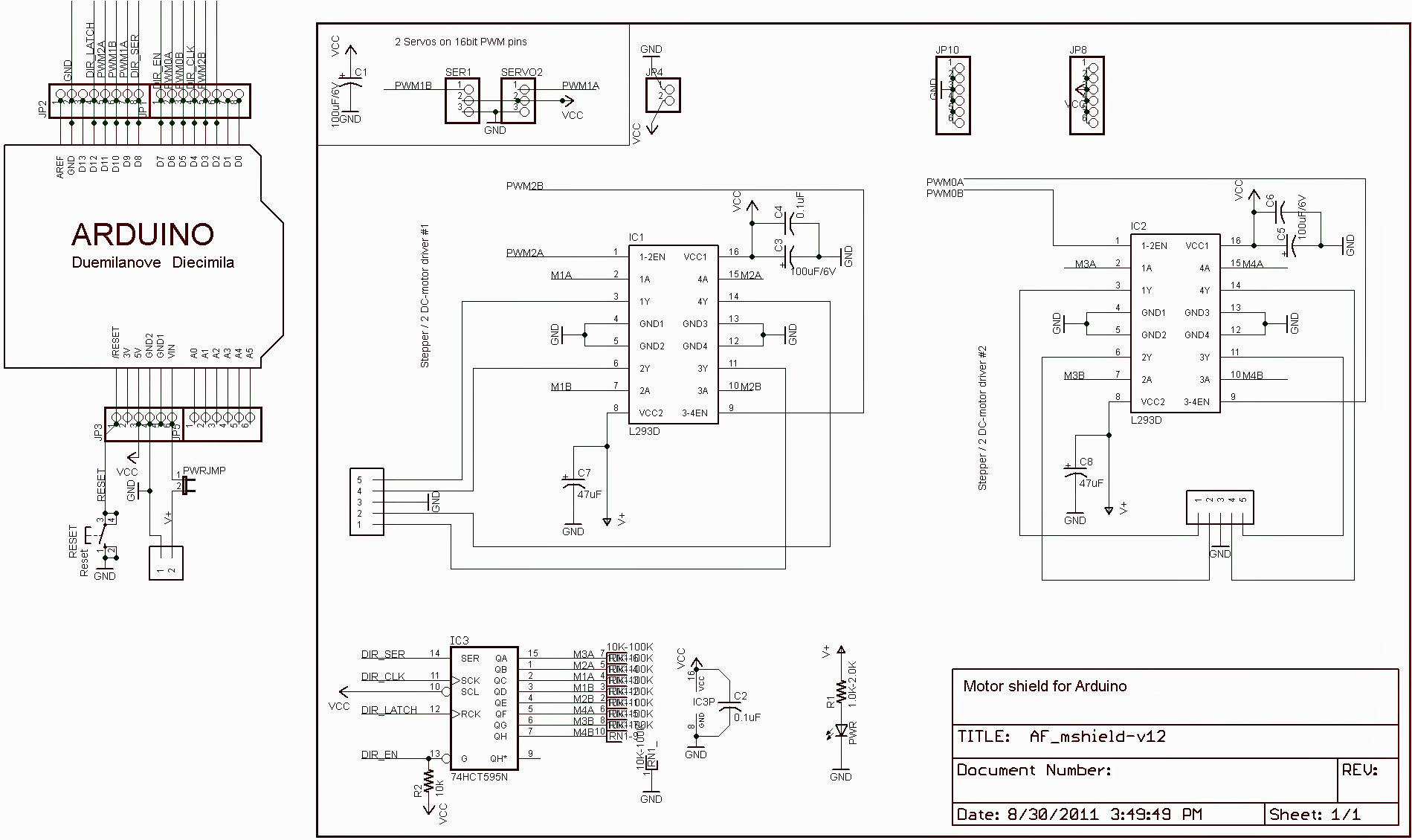
上面主要有兩種chip:
- 74HCT595N *1
- 計數器轉換暫存器
- 相關連結
- L293D *2
- 每棵可控制兩顆直流馬達或是一顆四線式步進馬達
- 相關連結
MTADRL293D主要功能:
- RESET
- 與Arduino 的RESET接在一起
- POWER JUMP
- 接上代表MTADRL293D的電池同時供電給arduino
- 電池正極(V+)接到Arduino VIN(Arduino內部可以自己轉成5V VCC)
- 兩路servo控制(只是幫忙轉換腳位,實際上還是使用Arduino 輸出的PWM控制)
- servo 1:直接接到Arduino pin 10
- servo 2:直接接到Arduino pin 9
- servo VCC: Arduino 5V <==不是直接接到MTADRL293D的BATT,或是由他降壓
- 四路馬達控制:
- M1
- EN: (PWM2A) 接到Arduino pin 11
- 電源: V+
- M2
- EN: (PWM2B) 接到Arduino pin 3
- 電源: V+
- M4
- EN: (PWM0B) 接到Arduino pin 5
- 電源: V+
- M3
- EN: (PWM0A) 接到Arduino pin 6
- 電源: V+
- 兩路四線式步進馬達控制
- 待續...
控制範例:
#include "MTADRL293D.h"

MTADRL293D l293d;

void setup(){

  Serial.begin(115200);
  while (!Serial){
    ;
  }

  delay(5000);

  Serial.println("=== loop() ===");

  l293d.enableDbg(true);
  l293d.begin();

  l293d.setMotorDir(MTADRL293D_M1, MTADRL293D_DIR_POS);
  l293d.setMotorDir(MTADRL293D_M2, MTADRL293D_DIR_POS);
  l293d.setMotorDir(MTADRL293D_M3, MTADRL293D_DIR_POS);
  l293d.setMotorDir(MTADRL293D_M4, MTADRL293D_DIR_POS);

  l293d.setMinMotorSpeed(MTADRL293D_M1, 100);
  l293d.setMinMotorSpeed(MTADRL293D_M2, 100);
  l293d.setMinMotorSpeed(MTADRL293D_M3, 100);
  l293d.setMinMotorSpeed(MTADRL293D_M4, 100);

  l293d.setMotorSpeed(MTADRL293D_M1, 0);
  l293d.setMotorSpeed(MTADRL293D_M2, 0);
  l293d.setMotorSpeed(MTADRL293D_M3, 0);
  l293d.setMotorSpeed(MTADRL293D_M4, 0);
}


void loop(){
  Serial.println("=== loop() ===");

  Serial.println("=== m1 pos 100");
  l293d.setMotorDir(MTADRL293D_M1, MTADRL293D_DIR_POS);
  l293d.setMotorSpeed(MTADRL293D_M1, 100);
  delay(3000);

  Serial.println("=== m1 0");
  l293d.setMotorSpeed(MTADRL293D_M1, 0);
  delay(1000);

  Serial.println("=== m1 neg 100");
  l293d.setMotorDir(MTADRL293D_M1, MTADRL293D_DIR_NEG);
  l293d.setMotorSpeed(MTADRL293D_M1, 100);
  delay(3000);

  Serial.println("=== m1 0");
  l293d.setMotorSpeed(MTADRL293D_M1, 0);
  delay(1000);

  Serial.println("=== m3 pos 100");
  l293d.setMotorDir(MTADRL293D_M3, MTADRL293D_DIR_POS);
  l293d.setMotorSpeed(MTADRL293D_M3, 100);
  delay(3000);

  Serial.println("=== m3 0");
  l293d.setMotorSpeed(MTADRL293D_M3, 0);
  delay(1000);

  Serial.println("=== m3 neg 100");
  l293d.setMotorDir(MTADRL293D_M3, MTADRL293D_DIR_NEG);
  l293d.setMotorSpeed(MTADRL293D_M3, 100);
  delay(3000);

  Serial.println("=== m3 0");
  l293d.setMotorSpeed(MTADRL293D_M3, 0);
  delay(1000);

}
使用Arduino Leonardo連結HC-05 BT 模組 - 設定與測試
Arduino Leonardo有兩個serial port:
範例程式:
===========================================
void setup() {
//init PC serial
Serial.begin(38400); // to PC
//init BT module serical
Serial1.begin(38400); // to BT module <==確認藍芽模組baud rate設定正確
}
char inByte=0;
void loop() {
while(Serial1.available() > 0){
inByte = Serial1.read();
Serial.write(inByte);
}
while(Serial.available() > 0){
inByte = Serial.read();
Serial1.write(inByte);
}
}
ps.
網路上看到UNO RESET時,會直接將USB UART與PIN 0/1接通,直接當USB轉TTL版子使用,不知道Leonardo是否可以這樣用
http://coopermaa2nd.blogspot.tw/2012/07/arduino-as-usb-to-ttl-adapter.html
- Serial: 與PC連結的USB模擬
- Serial1: Leonardo pin 0/pin 1
可以透過Leonardo做中介,使用PC直接設定HC-05,也可使用PC測試HC-05在一般模式時是否可以正常運作
步驟:
- 將HC-05 TX/RX 接到Leonardo的RX(0)/TX(1)
- 將HC-05的SET拉HIGH(設定模式) or LOW(一般模式)
- Leonardo上電運行範例程式
- HC-05上電
模式:
- 設定模式
- 直接使用AT command設定
- 注意: 當設定HC-05時,PC終端機程式必須設成enter轉換為\r\n,這樣HC-05才會吃command
- 一般模式
- 可透過 BT SPP profile與遠端裝置溝通(PC or android or....)
- android market 上有好用的免費程式可以用
- https://play.google.com/store/apps/details?id=mobi.dzs.android.BLE_SPP_PRO
範例程式:
===========================================
void setup() {
//init PC serial
Serial.begin(38400); // to PC
//init BT module serical
Serial1.begin(38400); // to BT module <==確認藍芽模組baud rate設定正確
}
char inByte=0;
void loop() {
while(Serial1.available() > 0){
inByte = Serial1.read();
Serial.write(inByte);
}
while(Serial.available() > 0){
inByte = Serial.read();
Serial1.write(inByte);
}
}
ps.
網路上看到UNO RESET時,會直接將USB UART與PIN 0/1接通,直接當USB轉TTL版子使用,不知道Leonardo是否可以這樣用
http://coopermaa2nd.blogspot.tw/2012/07/arduino-as-usb-to-ttl-adapter.html
HC-05 BT module
通常買來的模組會加一塊子板轉成5V,並加入LED。
一般arduino/8051/pic IO運作在5V,所以買加上子板模組方便許多
主要pin
- TX: 接到控制板的RX
- RX: 接到控制板的TX
- VCC: 接到5V
- GND: 接到GND
- SET: 設定模式
HC-05有兩種模式:
- 控制模式: SET拉high(5V)後將模組上電
- 一般模式: SET拉low(0V)後將模組上電
控制模式中可以下AT command來設定模組,一般模式下如果BT與對方SPP接上,則可以當作無線的UART使用
注意!!!
使用AT command設定時,假設是接到PC設定,須在terminal內設定enter對應到\r\n,這樣HC-05才可以吃AT command
HC-05 所有支援的baud rate,通常預設是9600 or 38400,如果不行就只好全部試試看...
- 4800, 9600, 19200, 38400, 57600, 115200, 23400, 460800, 921600, 1382400
出場預設狀態:
①.设备类:0
②.查询码:0x009e8b33
③.模块工作角色:SlaveMode
④.连接模式:指定专用蓝牙设备连接模式
⑤.串口参数:波特率—38400bits/s;停止位:1位;校验位:无
⑥.配对码:“1234”
⑦.设备名称:“H-C-2010-06-01”
常用AT command:
- AT
- 測試模組是否存在,若存在就會回OK
- AT+ORGL
- 回復出場預設值
- AT+NAME
- 取得目前名稱(藍芽搜尋到的裝置名稱): AT+NAME?
- 設定名稱: AT+NAME="XXXXXX"
- AT+ROLE
- 取得目前工作模式: AT+ROLE?
- 設定目前工作模式: AT+ROLE=X
- 工作模式
- 0: SLAVE
- 1: MASTER
- 2: SLAVE-LOOP(同SLAVE,但會回傳所有收到的字,應該是測試用)
- AT+PSWD
- 查看目前密碼: AT+PSWD?
- 設定密碼: AT+PSWD="XXXX"
- AT+UART
- 設定UART: AT+UART=XXX,Y,Z
- XXX:
- baud rate: 4800, 9600, 19200, 38400, 57600, 115200, 23400, 460800, 921600, 1382400
- Y:
- stop bit
- 0: 1bit
- 1: 2bit
- Z:
- parity bit
- 0: none
- 1: odd
- 2: even
相關文件
- 模組介紹
- http://www.wavesen.com/mysys/db_picture/news3/2013911141224101.pdf
- http://www.exp-tech.de/service/datasheet/HC-Serial-Bluetooth-Products.pdf
- at command
- http://www.wavesen.com/mysys/db_picture/news3/2013911155224101.pdf
- 網路相關文章
- https://mbed.org/users/edodm85/notebook/HC-05-bluetooth/
- http://www.yfrobot.com/forum.php?mod=viewthread&tid=4
- http://taktak.co.uk/2013/bluetooth-module-hc-05-bt_board-1-5-configuration/
- http://www.instructables.com/id/Arduino-AND-Bluetooth-HC-05-Connecting-easily/
ARDUINO 基礎
主站
http://arduino.cc/
基本語法與API
http://arduino.cc/en/Reference/HomePage
版子介紹
http://arduino.cc/en/Main/Products
參考網站
http://coopermaa2nd.blogspot.tw/
http://arduino.tw/
http://yourduino.com/sunshop2/index.php?l=page_view&p=education_pages
http://arduino.cc/
基本語法與API
http://arduino.cc/en/Reference/HomePage
版子介紹
http://arduino.cc/en/Main/Products
參考網站
http://coopermaa2nd.blogspot.tw/
http://arduino.tw/
http://yourduino.com/sunshop2/index.php?l=page_view&p=education_pages
訂閱:
意見 (Atom)